Radar Reflector Test Redux
Another Case Where Bigger is Better
“Safety Moments, presented at CCA Stations and Posts”
By Chuck Hawley, San Francisco Station
About 30 years ago, I participated in a test of radar reflectors with CCA members Stan Honey (SAF) and Jim Corenman (PNW) using a radar range at Stanford Research International (SRI). Stan’s uncle, Dick Honey, was a Senior Principal Scientist at SRI, and was give us access to a very high tech (for the 90s) testing facility that would normally be used to see how stealthy various pieces of military hardware were (how little radar cross section they had) as opposed to how MUCH radar energy could be reflected from something designed to be as un-stealthy as possible. To be allowed access to the radar range and engineers to help us operate it was an extremely fortuitous opportunity.
The “room” where we did the testing was perhaps 40’ long, 20’ high, and 20’ wide. The entire inside was covered with anechoic foam pyramids, designed to absorb all of the energy that the object that was being tested reflected, except for the small amount that was reflected back to the source of the energy. (Imagine that you are using a radar to try to find a buoy at night. What you’re interested in is the energy that is reflected directly back to the radar, as opposed to the radar energy that is reflected everywhere else.)
We borrowed about 10 off-the-shelf marine radar reflectors from West Marine for the test. These included some models that are still on the market today. We tested each of them at the two common frequencies used by vessels: X-band which is used in yachting radars, and S-band, which is used by ships. Each is important in different conditions and good performance in both bands is desirable.
One challenge is that what radar reflector is trying to do is not easy due to Physics, especially when the distance between the source of the radar, e.g. the ship, and the target of the radar, e.g. the yacht, increases. This is because of the inverse square law, which in layman’s terms, means that beams of energy spread out and get weaker over distances. We fundamentally understand this: a flashlight beam gets dimmer as it shines farther. However, with a radar reflector, the energy that is reflected back is also decreasing on the way back to the source, so instead of the rule being an inverse square law, this means that it’s an inverse fourth power law. In other words, to see an item (ship, iceberg, buoy, radar reflector) at twice the distance, it has to have 16x the radar reflectivity.
One of the concepts we had to become familiar with is the Radar Cross Section or RCS. This is measured in square meters. The “standard” is to measure the RCS of a conductive 1 sq m sphere. Why a sphere? That’s because a sphere is uniform in its “reflectivity” independent of its orientation to the source of the radar signal. So, we used the same conductive 1 sq m sphere that SRI used to calibrate our tests.
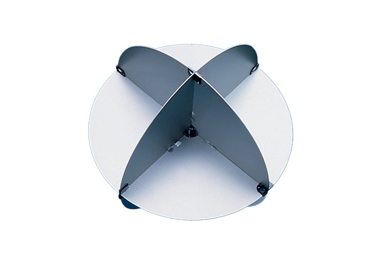
When it comes to radar reflectors, size matters. A lot. We know that many physical properties increase by the square of a linear dimension; for example, the area of a square table increases by the square of its width or length. We know that the volume of a sphere goes up by the cube of the diameter. However, with radar reflectors, the RCS goes up by the fourth power of its size. Imagine that you had a conventional octahedral radar reflector, like the Davis Echomaster. To double its RCS, you’d have to increase its diameter by only 19%.
But there’s another physical law that you have to contend with. To effectively reflect an electromagnetic wave, the reflector has to be a couple of wavelengths in size. The wavelength of a X-band radar (used by yachts) is about 1 ¼”. That means that an effective reflector has to be close to 3” across to reflect a yacht’s radar. This situation is exacerbated by the use of S-band radar (used by ships), which has a 4” wavelength. To effectively provide a radar return to a ship, the radar reflector needs to be at least 8” across and preferably larger. As the report says, “small detectors must be looked at with a great deal of suspicion, as there is no substitute for size.”
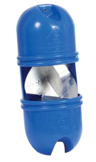
Finally, the orientation of the radar reflector is very important to its effectiveness, especially when you think of a heeled sailboat or a rolling and pitching powerboat. Many CCA members will have heard of the “catch rain” position for an octahedral radar reflector. For a powerboat that doesn’t heel, orienting an octahedral reflector with one of its “pockets” upward provides the best average RCS as the boat rotates with respect to the radar source. However, for a sailboat that may be heeled over 15 or more degrees on a passage, the “double catch rain” position may be more effective (on average). Think of this orientation as having one “edge” upward and aligned with the fore and aft axis of the boat. As the boat heels, the reflector assumes the “catch rain” orientation on either tack.
We did not test various electronic devices that are intended to overcome the challenges of small radar reflectors. Now it’s possible to buy SARTs (Search and Rescue Transponders) and RTEs (Radar Target Enhancers), not to mention the widespread use of AIS (automatic Identification System) for yachts. Those technologies have advantages over the non-electronic, relatively inexpensive, not-very-attractive radar reflectors. But if you want to enhance the likelihood of being “seen” by another vessel’s radar, with electronics or batteries, the lowly radar reflector is still a good shipboard companion.
See the complete report by clicking here or read it only at US Sailing:
https://www.ussailing.org/wp-content/uploads/2018/03/radar-reflector-tests.pdf
The Cruising Club of America is a group of accomplished recreational offshore sailors bound together by friendship and the desire to foster the responsibilities, expertise, and skills needed for the adventurous use of the sea. Safety Moments are brief updates on marine safety issues, presented by station Safety Officers at meetings. They are published by the CCA Safety and Seamanship Committee and are intended to advance seamanship and safety by highlighting new technologies, suggestions for safe operation and reports of maritime disasters around the world.